")


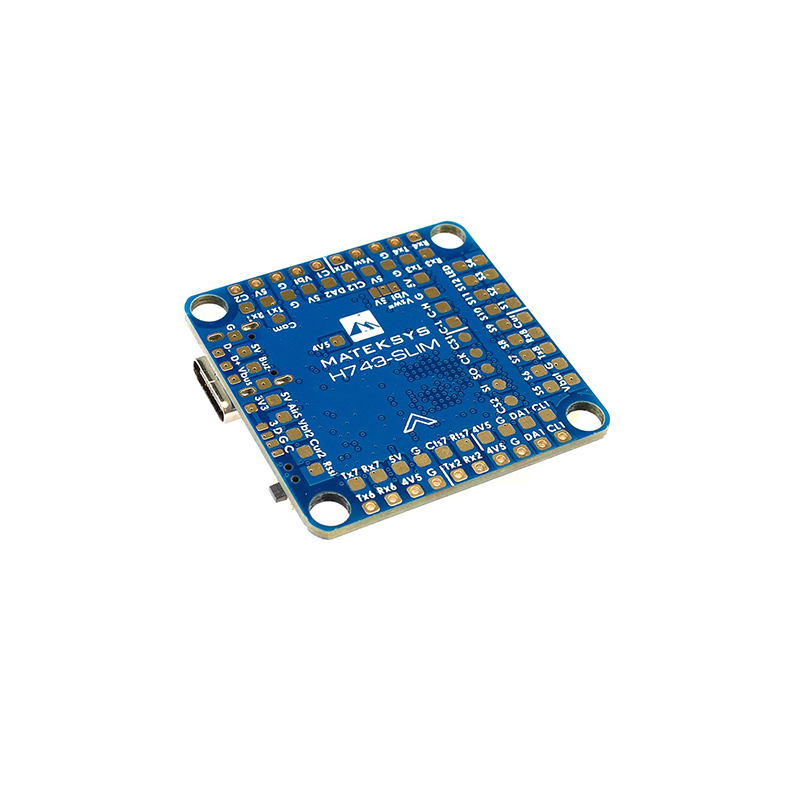
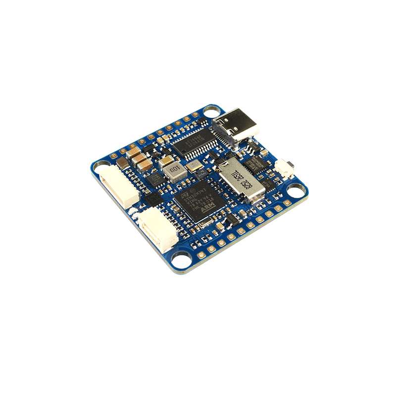
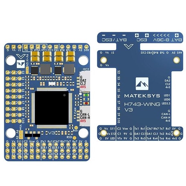
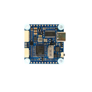
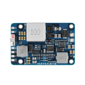
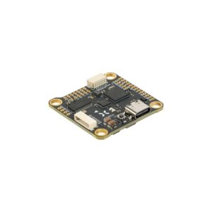
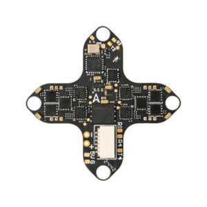
Mateksys Flight Controller H743-SLIM V3
Experience high-performance flight control with dual IMUs, 13 PWM outputs, DJI FPV OSD support, and versatile firmware compatibility.
$174.99
In Stock at KiwiQuads
Description
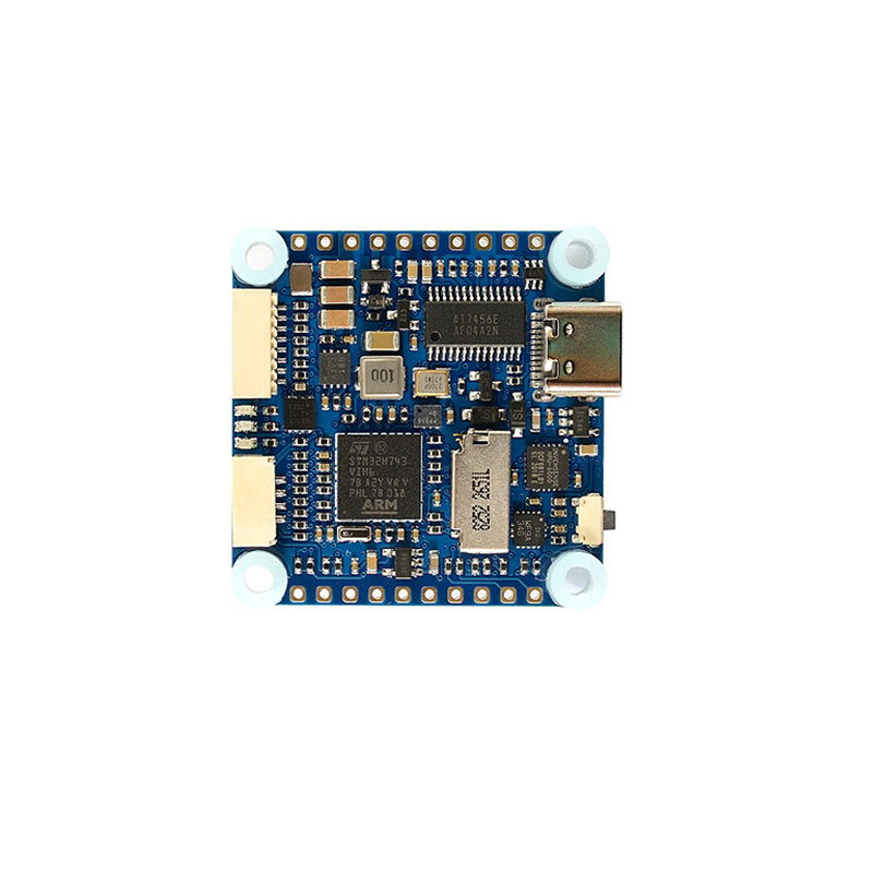
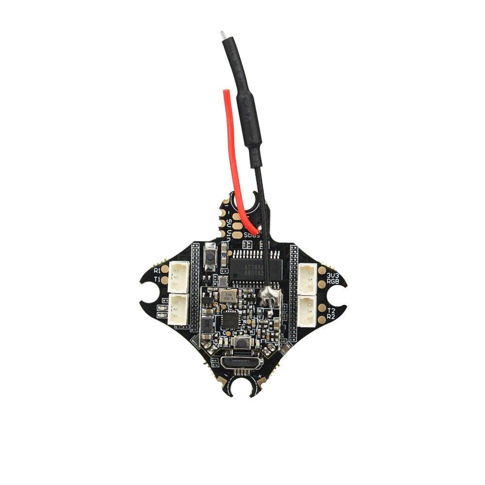
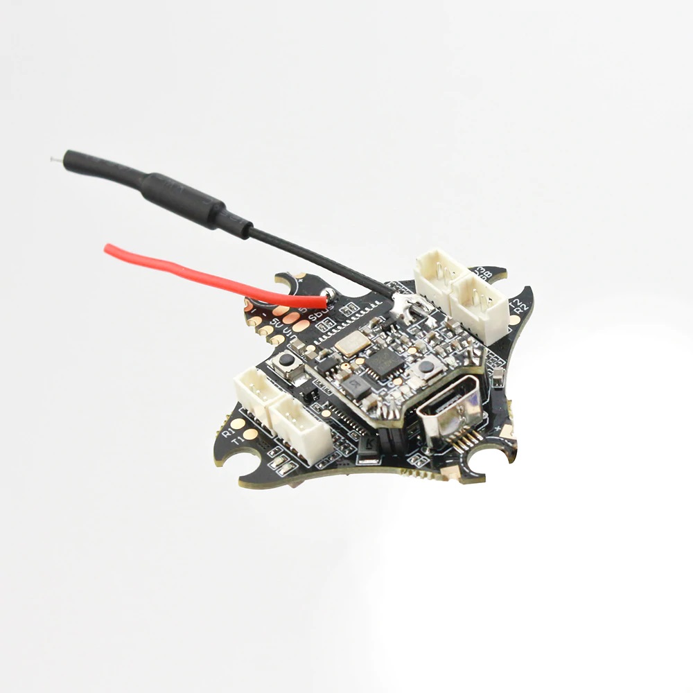
The Mateksys Flight Controller H743-SLIM V3 delivers unmatched power and precision with its STM32H743VIH6 MCU running at 480MHz, dual IMUs, and extensive UART support. Designed for flexibility, it features a microSD blackbox, dual camera inputs, DJI FPV OSD compatibility, and 13 PWM outputs—perfect for high-performance drone builds. With a robust 6-36V input range and optimized firmware support for ArduPilot, Betaflight, and INAV, it’s the ultimate choice for elite pilots.
Specifications
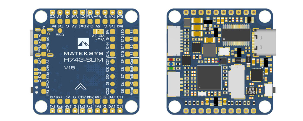
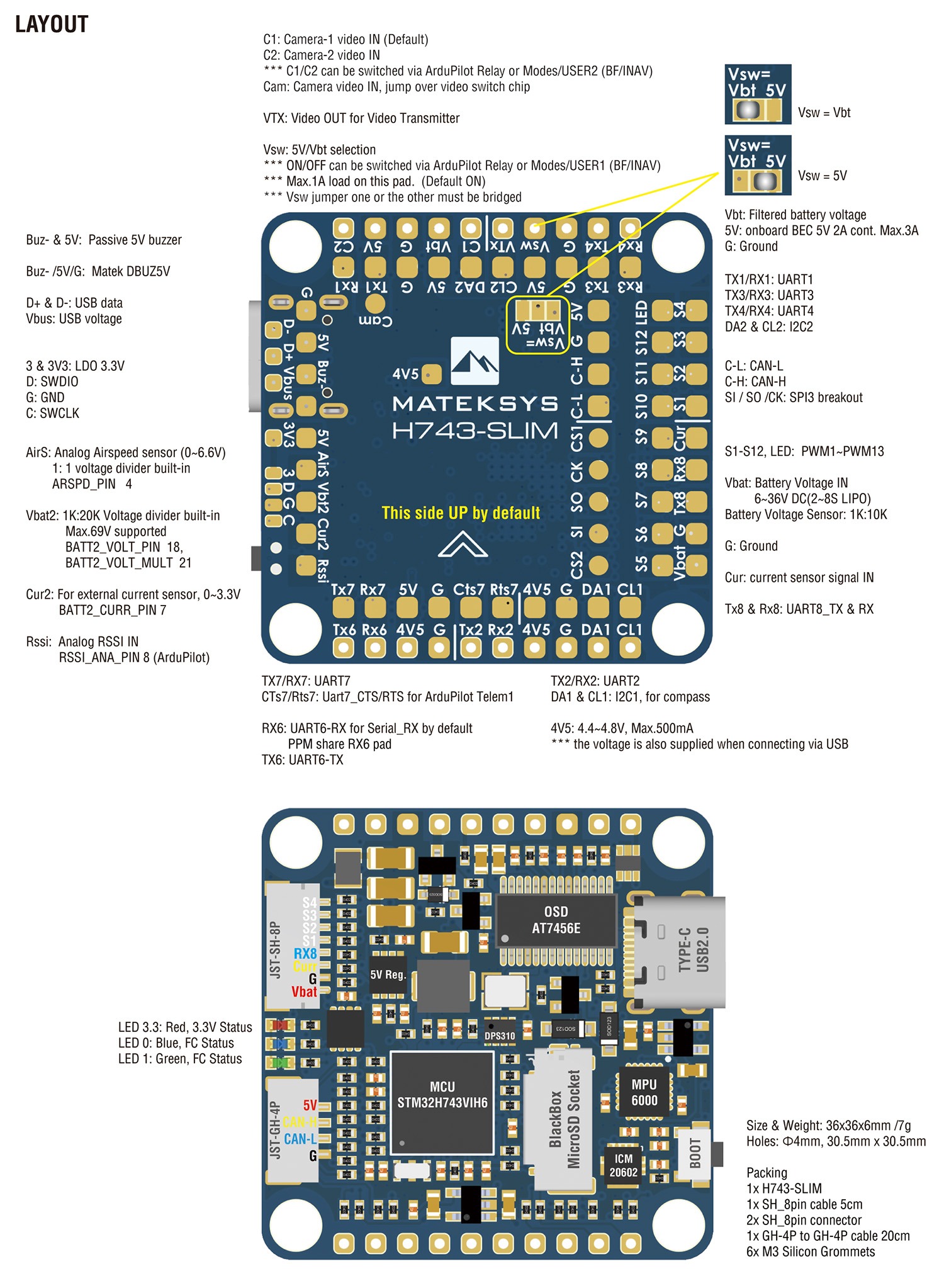
- MCU: STM32H743VIH6, 480MHz , 1MB RAM, 2MB Flash
- Board V1.0 IMU: MPU6000 (SPI1) & ICM20602 (SPI4)
- Board V1.5 IMU: MPU6000 (SPI1) & ICM42605 (SPI4)
- Baro: Infineon DPS310 (I2C2)
- OSD: AT7456E (SPI2)
- Blackbox: MicroSD card socket (SDIO)
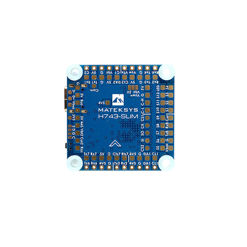
- 7x Uarts (1,2,3,4,6,7,8) with built-in inversion.
- 13x PWM outputs(including “LED” pad)
- 2x I2C
- 1x CAN
- 6x ADC (VBAT, Current, RSSI, Analog AirSpeed, Vbat2, Cur2)
- 3x LEDs for FC STATUS (Blue, Red) and 3.3V indicator(Red)
- 1x SPI3 breakout
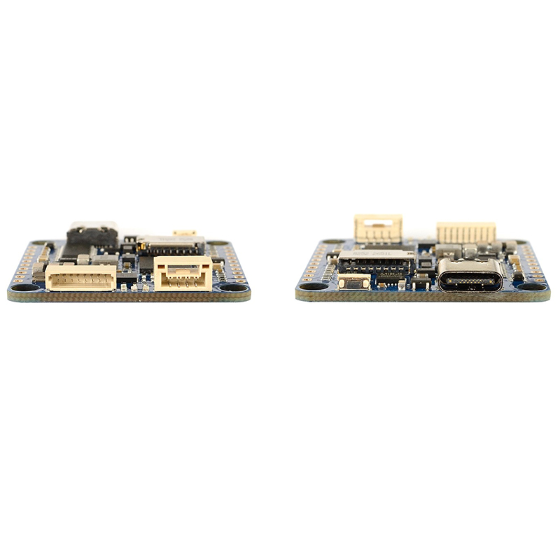
- USB Type-C(USB2.0)
- 1x JST-SH1.0_8pin connector (Vbat/G/Curr/Rx8/S1/S2/S3/S4)
- 1x JST-GH1.25_4pin connector (5V/CAN-H/CAN-L/G)
- Dual Camera Inputs switch
- 5V/Vbat filtered power ON/OFF switch
- DJI FPV OSD is supported by any spare UART
Power
- Vbat Input: 6~36V (2~8S LiPo)
- BEC: 5V 2A cont. (Max.3A)
- LDO 3.3V: Max.200mA
- No Current Sensor built-in
- ADC Vbat2 pad supports Max. 69V (voltage divider: 1K:20K)
- Static power: 200mA@5V with Betaflight, 150mA@5V with ArduPilot
FC Firmware
- ArduPilot(ChiBiOS): MATEKH743
- BetaFlight: MATEKH743
- INAV: MATEKH743
Physical
- Mounting: 30.5 x 30.5mm, Φ4mm with Grommets Φ3mm
- Dimensions: 36 x 36 x 5 mm
- Weight: 7g
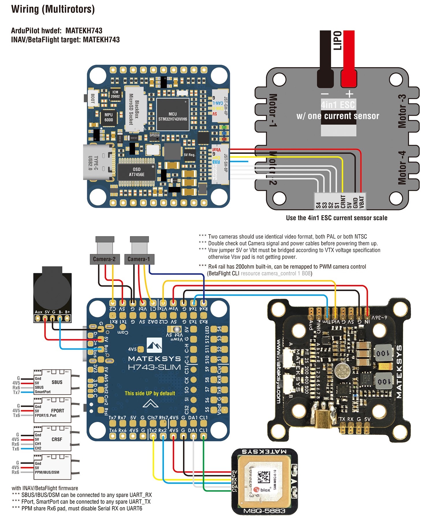
ArduPilot Relay
- Camera-1 and Vsw On by default
- Make sure 2 cameras are set with identical video format, both PAL or both NTSC.
# GPIOs
- PD10 PINIO1 OUTPUT GPIO(81) //Vsw pad power switch
- PD11 PINIO2 OUTPUT GPIO(82) //Camera switch
# RCx_OPTION: RC input option
- 28 Relay1 On/Off
- 34 Relay2 On/Off
- 35 Relay3 On/Off
- 36 Relay4 On/Off
e.g.
- RELAY1_PIN 81 //Vsw GPIO
- RC7_OPTION 28 //Relay On/Off, Use CH7 of Transmitter to switch Vsw
- RELAY2_PIN 82 //Camera switch GPIO
- RC8_OPTION 34 //Relay2 On/Off, Use CH8 of Transmitter to switch camera
or
- RELAY3_PIN 81 //Vsw GPIO
- RC9_OPTION 35 //Relay3 On/Off, Use CH9 of Transmitter to switch Vsw
- RELAY4_PIN 82 //Camera switch GPIO
- RC10_OPTION 36 //Relay4 On/Off, Use CH10 of Transmitter to switch camera
The configured feature will be triggered when the auxiliary switch’s pwm value becomes higher than 1800. It will be deactivated when the value falls below 1200.
Check the pwm value sent from the transmitter when the switch is high and low using the Mission Planner’s Initial Setup >> Mandatory Hardware >> Radio Calibration screen. If it does not climb higher than 1800 or lower than 1200, it is best to adjust the servo end points in the transmitter.
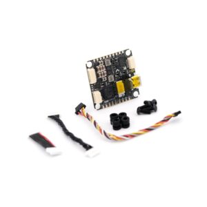
Package Includes:
- 1 x H743-SLIM
- 6 x Silicon grommets M4 to M3
- 1 x JST-SH1.0_8pin cable, 5cm
- 2 x JST-SH1.0_8pin connectors
- 1 x JST-GH-4P to JST-GH-4P cable for CAN port, 20cm
Additional information
| Brand |
|---|
Only logged in customers who have purchased this product may leave a review.
Related products
-
Tinyhawk III Spare Parts – AIO Flight Controller and VTX
(3) $139.99In stockAdd to cart -
Flywoo GOKU GN745 45A AIO V3 MPU6000 (AM32)
$199.99Out of stockRead more -
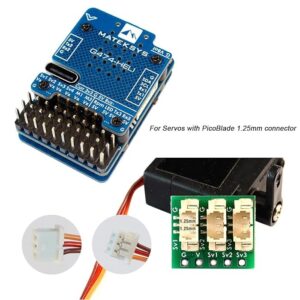
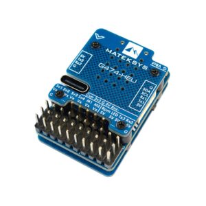
Mateksys RC Helicopter Flybarless Controller G474-HELI
(1) $94.99In stockAdd to cart -
Sale!
Mateksys F405-WING-V2 Flight Controller
Original price was: $109.99.$89.99Current price is: $89.99.In stockAdd to cart -
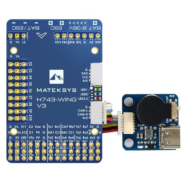
Mateksys H743-WING V3 Flight Controller
(3) $219.99Out of stockRead more -
Sale!
Mateksys F405-TE Quad Flight Controller
Original price was: $119.99.$99.99Current price is: $99.99.In stockAdd to cart
Explore more from Mateksys
-
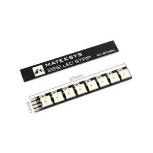
Mateksys 2812 8-LED Board Slim (Qty 2)
$8.99In stockAdd to cart -
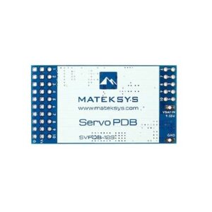
Mateksys Servo PDB w/ 12A BEC 9-55V to 5/6/8V
$39.99In stockAdd to cart -

Mateksys Flight Controller H743-SLIM V3
$174.99In stockAdd to cart -
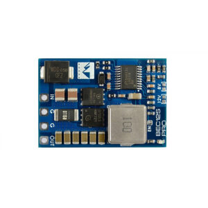
Mateksys BEC PRO 12S to 5/8/12V-5A
(1) $34.99In stockAdd to cart -
Mateksys Power Module 12S w/ 3xBEC
$92.99In stockAdd to cart -
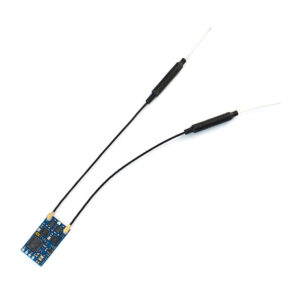
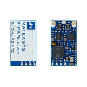
Mateksys ExpressLRS 2.4G True Diversity Receiver
$48.99In stockAdd to cart
Other 30mm Flight Controllers you might like
-
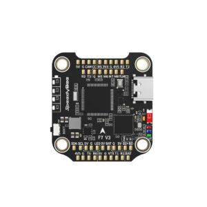
SpeedyBee F7 V3 Flight Controller
$119.99Out of stockRead more -
Mateksys F405-HDTE Quad Flight Controller for DJI
(1) $119.99In stockAdd to cart -
Sale!
Mateksys F405-TE Quad Flight Controller
Original price was: $119.99.$99.99Current price is: $99.99.In stockAdd to cart -
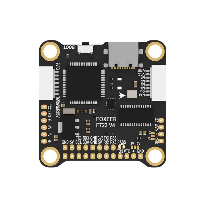
Foxeer F722 V4 Flight Controller X8 DJI Type-C
(4) $109.99Out of stockRead more -
 Sale!
Sale!
Foxeer H7 MPU6000 FC 8S Dual BEC Barometer X8
Original price was: $199.99.$129.99Current price is: $129.99.Out of stockRead more -
TBS Lucid H7 Flight Controller
(1) $124.99In stockAdd to cart
Other Electronics you might like
-
TBS Solder – Premium Leaded Solder 100g (0.5mm)
(33) $15.99Out of stockRead more -
Mateksys Micro BEC 12S/60V Input to 5V/9V/12V
(3) $14.99In stockAdd to cart -
Foxeer F405 V2 FC Reaper 55A ESC Stack
$149.99In stockAdd to cart -
Flywoo GOKU GN745 45A AIO V3 MPU6000 (AM32)
$199.99Out of stockRead more -
 Sale!
Sale!
iFlight RGB LED Power Module for Backpack
(4) Original price was: $29.99.$19.99Current price is: $19.99.In stockAdd to cart -
SpeedyBee BL32 F4 128kHz 50A 4-in-1 ESC 30×30
$124.99In stockAdd to cart
Other Flight Controllers you might like
-
Sale!
Mateksys F405-TE Quad Flight Controller
Original price was: $119.99.$99.99Current price is: $99.99.In stockAdd to cart -
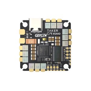
GepRC TAKER G4 45A 8Bit AIO
$139.99Out of stockRead more -
EMAX TinyHawk 2 AIO FC + VTX
(15) $139.99Out of stockRead more -
BetaFPV Matrix 1S Brushless Flight Controller G4 3IN1 HD V1.0
$89.99In stockAdd to cart -
HDZero Halo Mini Flight Controller
$149.99In stockAdd to cart -
Radiomaster WT100 Wireless Handheld Remote + RX
$199.99Out of stockRead more
Reviews
There are no reviews yet.